¶ Header
Your content here

¶ Analog input connection
Analog input usually serves for reading Voltage 0-10 V, Current 0-20 mA or resistance sensors (e.g.
temperature sensor Pt1000). Type of measurement is configured depending on used software.
Negative pole of measured external device is to be connected to screw connector of AGND while
positive pole is to be connected to screw AIY.X connector.
In default Neuron is set to voltage measurement to avoid potential device / sensor damage in case of inappropriate external device.
Depending on type of output value (either voltage or current) of external device it is first necessary to check measurement configuration of Neuron through the chosen software before actual connection of
the external device.
- Voltage 0 – 10 V
- Current 0 – 20 mA
¶ Measuring on analog inputs other than group 1
No available in legacy mode
Analog inputs of groups other than group 1 provides precise measurement of voltage, current and
resistance. The type of measurement is set according the used SW in register AI mode according to
the following table. The value read from register Analog Input equals the actual measured value in
displayed in the table.
- Off
- Voltage 0 – 10 V
- Voltage 0 – 2.5 V
- Current 0 – 20 mA
- Resistance (two conductors) 0 – 1 960 Ω
- Resistance (three conductors) 0 – 100 kΩ
¶ Digital output connection
Digital outputs (semiconductor, connected as opened collectors) are accessible through DoX (DoY.X),
DoGND and possibly FBD screw connectors of Digital I/O’s. All digital outputs have common screw
connector DoGND for negative pole connection of DC power supply. Screw connector of DoX serves
for connection of electrical load of external device, which switches against the common potential. State switch of each output is signalized via corresponding indication LED diode atop the device.
¶ Digital input connection
To digital inputs are usually connected devices such e.g. switches (light switches, buttons), motion sensors, door contacts, and window contacts etc. Logic state 1 (switched on) of each input is signalized via relevant indication LED diode on the top side of the product case.
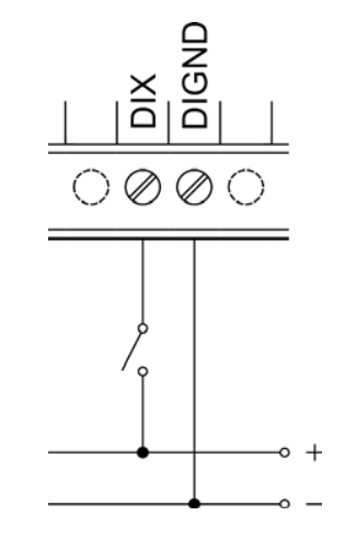
For the connection of external device to digital input there are screw connectors marked with DiX (or possibly DiY.X) and DiGND. All digital input connectors share a common ground connector for connection of negative pole of DC voltage source. Voltage source positive pole is to be connected over external device to DiX connector as shows the picture below.

For signalization of state of external devices connected to digital inputs we recommend different voltage to provide proper galvanic isolation.
Some models feature its own 24V DC power source for use with digital inputs. Its output leads to screw connectors DIVGND and DIVOUT. For correct functioning of digital inputs with this power supply it is also necessary to interconnect DIVGND and DIGND. Maximum current on each of the DIVOUT screw connectors is limited to 120 mA which is enough for 30 digital inputs.
¶ Digital input functions
Correct functioning of digital inputs depends on configuration of Debounce variable depending on
connected switch and on the environment in which the device is installed
¶ Debounce
No available in legacy mode
Function Debounce serves for input flash repression, its value is presented in hundreds of µs (i.e. value 100 equals 10 ms). Impulse (positive edge) is processed as valid only in case it equals logical 1 for the whole set duration.
¶ Relay output connection
Relay outputs are to be connected to RoY.X and COM screw connectors and serve for switching twostate components with either AC or DC voltage. COM screw connector serves supply of switched voltage for devices connected to the same connector. Screw connector of RoY.X serves for conducting
of switched voltage of the given relay output. Relays are connected in NO wiring thus their output equals zero when switched off.
Corresponding indication LED diode atop the Neuron device lights up when the output is switched on.
It is optimal to accomplish overload and short circuit protection through external circuit breaker
separately for each Relay output, or possibly for the whole RO group. Rated current and type of the
circuit breaker is to be chosen appropriately according to electrical load and its characteristics while considering maximum current of the output, eventually group of outputs.