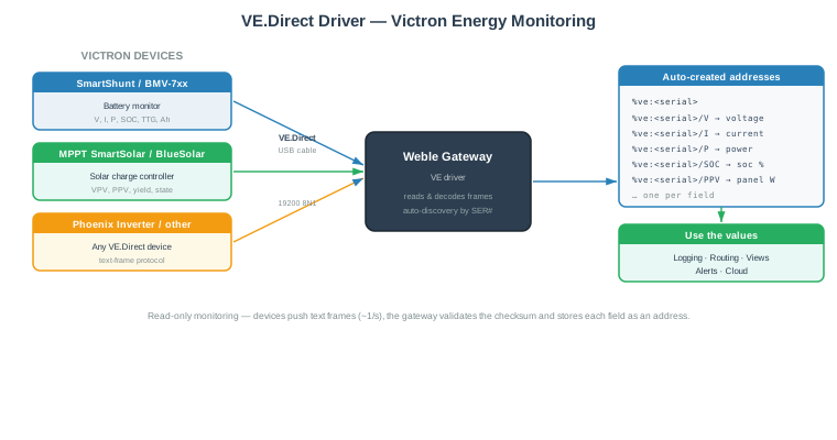
VE.Direct is the serial text protocol used by Victron Energy devices to publish their live measurements. The Weble universal gateway VE driver connects to a Victron device over a VE.Direct-to-USB cable, reads the periodic data frames, validates their checksum, decodes every field, and exposes each measurement as a gateway address.
The driver is read-only and works by auto-discovery: as soon as a device starts transmitting, the gateway identifies it by its serial number and automatically creates one address per field. No manual address entry is required.
Typical supported devices:
- SmartShunt and BMV-7xx battery monitors — voltage, current, power, state of charge, time-to-go, consumed Ah, history.
- MPPT SmartSolar / BlueSolar solar charge controllers — panel voltage/power, charge state, daily and total yield.
- Phoenix inverters and any other device exposing a VE.Direct text interface.
¶ 1. Getting started
¶ 1.1 Wiring
VE.Direct is a 3.3 V TTL serial interface. Connect the Victron device to the gateway with an original VE.Direct-to-USB interface cable (Victron part ASS030530000). The cable presents itself as a USB serial port on the gateway.
The protocol runs at a fixed 19200 baud, 8 data bits, no parity, 1 stop bit (8N1) — these are the driver defaults and normally never need to be changed.
One VE.Direct cable carries a single device. To monitor several Victron devices, use one cable and one gateway per device.
¶ 1.2 Gateway configuration
- Create a new gateway and select the VE driver.
- In Serial Port, pick the VE.Direct-to-USB cable from the auto-complete list of detected USB/serial interfaces.
- Leave BaudRate at
19200, Parity atnoneand Stopbit at1(VE.Direct standard). - Start the gateway.
Once running, the gateway waits for the device's data frames. As soon as a valid frame is received, the device is identified by its serial number and its addresses appear automatically.
¶ 1.3 Reading the values
The driver creates a small tree of addresses per device (see section 3). For example, a SmartShunt with serial HQ2013ABCDE produces:
%ve:HQ2013ABCDE— the full snapshot (all fields as one JSON object)%ve:HQ2013ABCDE/V— battery voltage (V)%ve:HQ2013ABCDE/I— battery current (A)%ve:HQ2013ABCDE/P— power (W)%ve:HQ2013ABCDE/SOC— state of charge (%)
These addresses can then be logged, routed, displayed in views and used in alerts like any other gateway value.
¶ 2. Gateway parameters
| Label | JSON Key | Description |
|---|---|---|
| Name | name | A descriptive name for this VE gateway instance. |
| Cluster ID | cluster | Cluster identifier. Use 0 for single-gateway setups. |
| Serial Port | json.serialPort | The VE.Direct-to-USB interface. The auto-complete lists detected USB/serial interfaces. |
| Parity | json.serialPortParity | Serial parity: none (VE.Direct standard), even or odd. Default: none. |
| BaudRate | json.serialPortBaudRade | Serial baudrate. VE.Direct standard is 19200. Values: 9600, 19200, 38400, 57600, 76800, 115200. |
| Stopbit | json.serialPortStopBit | Stop bits: 1 (standard) or 2. Default: 1. |
| idleTimeout | json.idleTimeout | Minimum interval, in milliseconds, between two stored value updates for a device. VE.Direct devices transmit roughly once per second; this throttles how often new values are emitted and logged. Default: 2000. |
¶ 2.1 Gateway JSON example
{
  "serialPort": "/dev/serial/by-id/usb-VictronEnergy_BV_VE_Direct_cable-if00",
  "serialPortBaudRade": 19200,
  "serialPortParity": "none",
  "serialPortStopBit": 1,
  "idleTimeout": 2000
}
¶ 3. Addresses
¶ 3.1 Address format
VE addresses use the prefix %ve: followed by the device serial number, and optionally a field suffix:
%ve:<serial> or %ve:<serial>/<FIELD>
%ve:<serial>— the full snapshot: a JSON object containing every field currently reported by the device.%ve:<serial>/<FIELD>— a single field, with its value already decoded to engineering units (e.g. millivolts converted to volts) and its unit attached.
<FIELD> is the raw VE.Direct label (V, I, P, SOC, H1 …). Each field address carries a human-readable description (e.g. voltage) and, where applicable, a unit.
Addresses are created automatically by device discovery. Manual address insertion and import are disabled; you can remove an address that is no longer needed.
¶ 3.2 Address parameters
| Label | JSON Key | Description |
|---|---|---|
| Name | name | The VE address (auto-discovered from the device). |
| Description | description | Optional description. |
| Log | log | Logging mode: never, on update, always, or a fixed duration in ms. |
¶ 3.3 Address properties
| Property | Value |
|---|---|
| Readable | No — values are pushed by the device, not polled |
| Writable | No — read-only monitoring |
| Routable | Yes |
| Loggable | Yes |
¶ 4. Field reference
The tables below list the VE.Direct fields the driver decodes. The exact set of fields depends on the device model — a battery monitor exposes the real-time and history fields, an MPPT charger exposes the solar fields. Values are already converted to the listed unit.
¶ 4.1 Real-time — battery monitor / shunt
| Field | Address suffix | Description | Unit |
|---|---|---|---|
| V | /V |
Main (battery) voltage | V |
| VS | /VS |
Auxiliary / starter battery voltage | V |
| VM | /VM |
Mid-point voltage | V |
| DM | /DM |
Mid-point deviation | % |
| I | /I |
Battery current (negative = discharge) | A |
| P | /P |
Instantaneous power | W |
| CE | /CE |
Consumed energy | Ah |
| SOC | /SOC |
State of charge | % |
| TTG | /TTG |
Time-to-go (∞ when charging) |
min |
| T | /T |
Battery temperature | °C |
| Alarm | /Alarm |
Alarm active | on/off |
| Relay | /Relay |
Relay state | on/off |
| AR | /AR |
Alarm reason code | — |
| MON | /MON |
Monitor mode | — |
¶ 4.2 History — battery monitor
| Field | Address suffix | Description | Unit |
|---|---|---|---|
| H1 | /H1 |
Deepest discharge | Ah |
| H2 | /H2 |
Last discharge | Ah |
| H3 | /H3 |
Average discharge | Ah |
| H4 | /H4 |
Number of charge cycles | — |
| H5 | /H5 |
Number of full discharges | — |
| H6 | /H6 |
Cumulative Ah drawn | Ah |
| H7 | /H7 |
Minimum battery voltage | V |
| H8 | /H8 |
Maximum battery voltage | V |
| H9 | /H9 |
Seconds since last full charge | s |
| H10 | /H10 |
Number of automatic synchronisations | — |
| H11 | /H11 |
Number of low-voltage alarms | — |
| H12 | /H12 |
Number of high-voltage alarms | — |
| H15 | /H15 |
Minimum auxiliary battery voltage | V |
| H16 | /H16 |
Maximum auxiliary battery voltage | V |
| H17 | /H17 |
Discharged energy | kWh |
| H18 | /H18 |
Charged energy | kWh |
¶ 4.3 Solar charge controller (MPPT)
| Field | Address suffix | Description | Unit |
|---|---|---|---|
| VPV | /VPV |
Panel voltage | V |
| PPV | /PPV |
Panel power | W |
| CS | /CS |
Charge state (see below) | — |
| MPPT | /MPPT |
Tracker operation mode | — |
| ERR | /ERR |
Error code | — |
| IL | /IL |
Load current | A |
| LOAD | /LOAD |
Load output state | on/off |
| OR | /OR |
Off reason | — |
| H19 | /H19 |
Yield total (lifetime) | kWh |
| H20 | /H20 |
Yield today | kWh |
| H21 | /H21 |
Maximum power today | W |
| H22 | /H22 |
Yield yesterday | kWh |
| H23 | /H23 |
Maximum power yesterday | W |
| HSDS | /HSDS |
Day sequence number | — |
¶ Charge state (CS) values
| Value | Meaning | Value | Meaning |
|---|---|---|---|
| 0 | Off | 6 | Storage |
| 1 | Low power | 7 | Equalize |
| 2 | Fault | 245 | Starting-up |
| 3 | Bulk | 247 | Auto equalize |
| 4 | Absorption | 252 | External control |
| 5 | Float |
¶ 4.4 Device identity
| Field | Address suffix | Description |
|---|---|---|
| PID | /PID |
Victron product ID |
| FW | /FW |
Firmware version |
| BMV | /BMV |
Model name |
| SER# | /SER# |
Device serial number |
¶ 5. How it works
- The Victron device transmits a text frame on the VE.Direct line about once per second. Each frame is a set of
label <tab> valuelines terminated by a Checksum field. - The driver reassembles each frame and verifies the checksum. Frames with an invalid checksum are discarded.
- Valid frames are decoded (raw integers are scaled to engineering units — for example voltage is reported in millivolts and converted to volts).
- The device is identified by its serial number (
SER#). The full snapshot is stored under%ve:<serial>and every field under%ve:<serial>/<FIELD>. - New values are emitted no more often than the idleTimeout interval, then made available to logging, routing, views and alerts.
If the device stays silent for more than 10 seconds the connection is considered stale; the driver keeps watching the port and resumes automatically as soon as frames arrive again.