The logic module, by the elaboration of simplified logic circuits, is a powerful tool that lets you program the universal IoT gateway as a PLC (Programmable Logic Controller). There is no fixed hard limits in terms of logic gates and number of circuits. With the aid of our interface web, it is easy to construct circuits which perform complexe operations / interactions between different IoT/building automation protocols. The example below ( Figure 1 ) illustrates how a simple task can be performed easily without requiring prior knowledge in computer programming.

Main functionalities offered by the logic module :
- Edition/Import/Export of logic circuits for automatisms (recurring actions).
- Design visual event based interactions between different building automation protocols / field buses (KNX, Modbus, SMTP, BACnet, MQTT, ADS, etc...).
- Task scheduling, using a simple date like format or using a CRON (linux format for task scheduling).
- Powerful custom JavaScript coding for developers using the programmable gate and the universal IoT gateway API.
This manual is divided in two main chapters, first a quick introduction to the logic module web interface to get started, followed by a complete explanation of the logic circuits and their operations.
Table of content :
¶ 1. Getting started
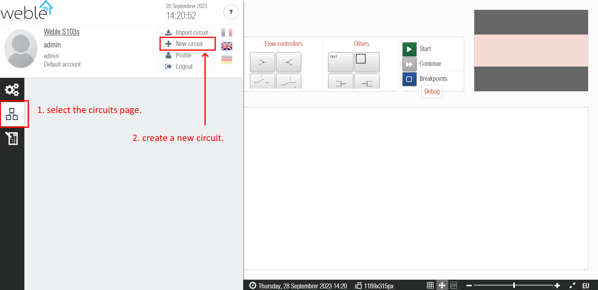
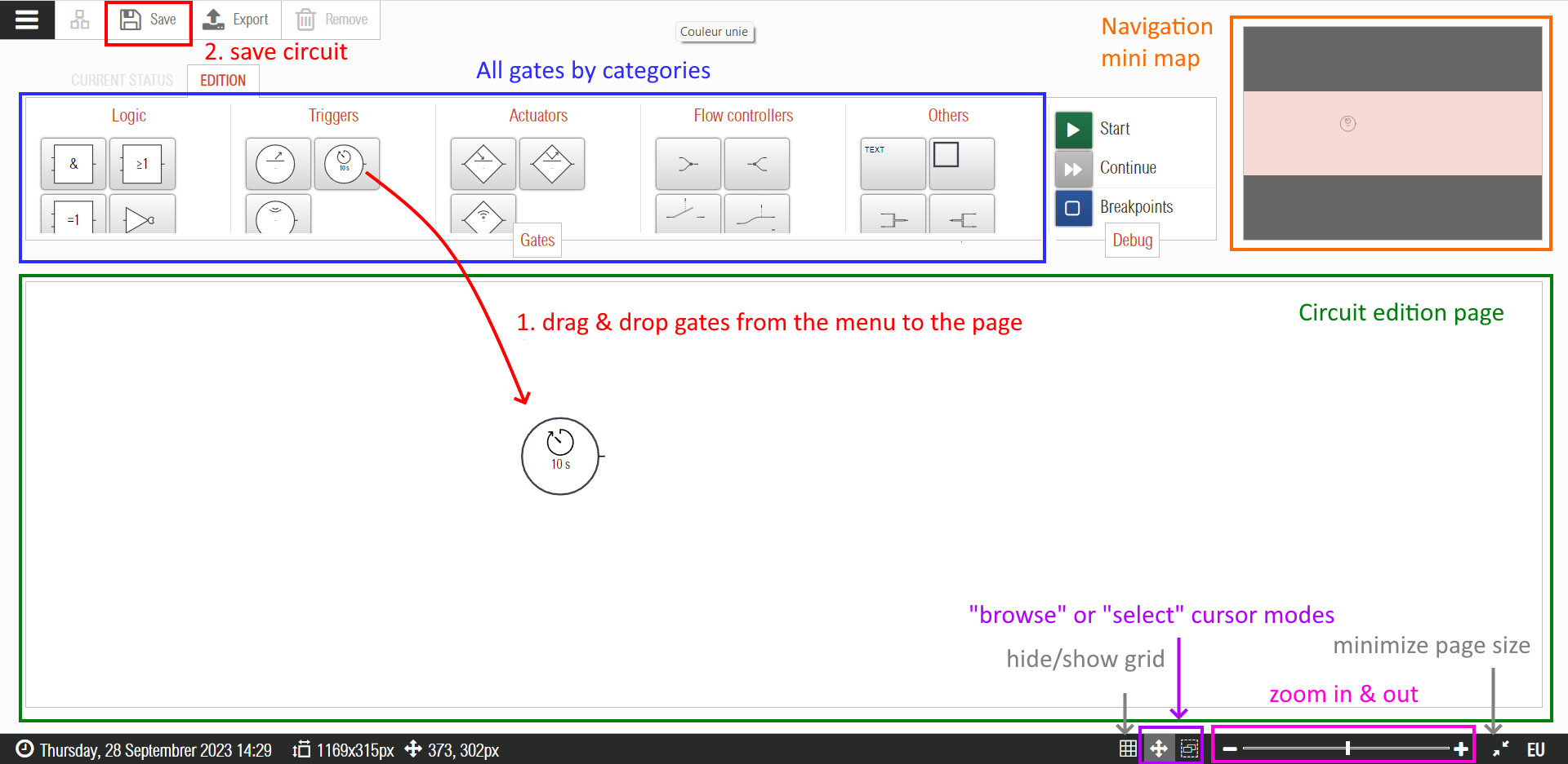
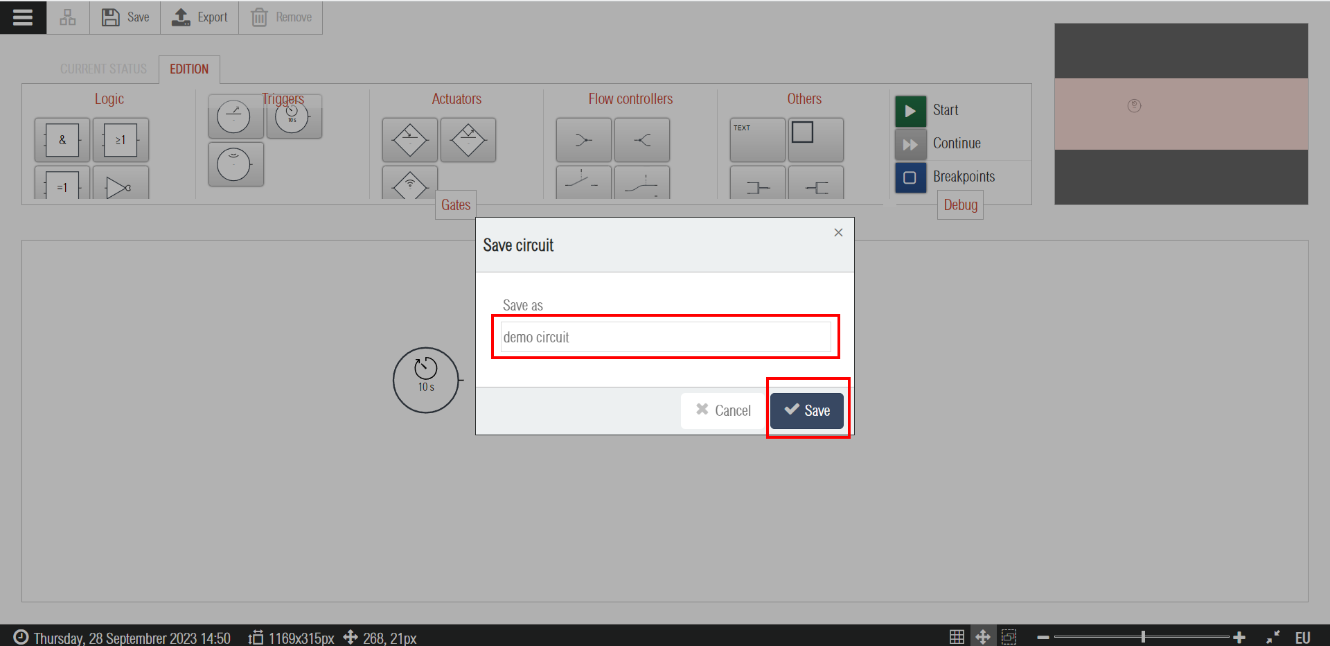
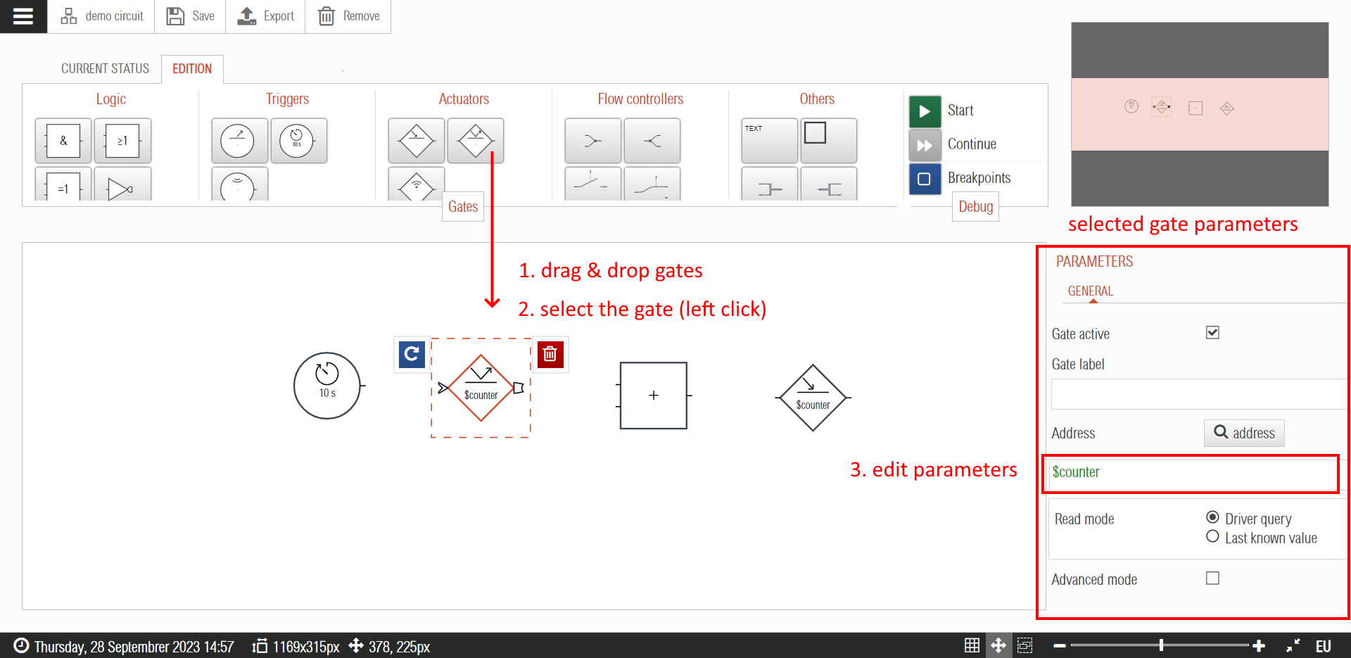
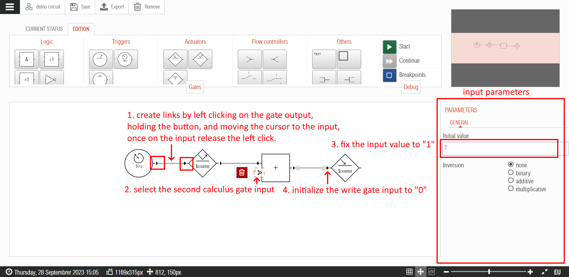
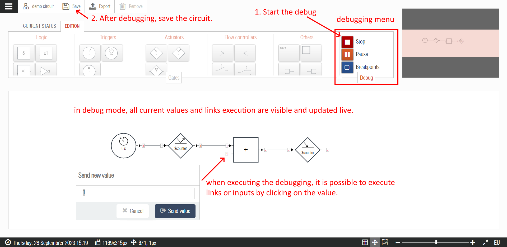
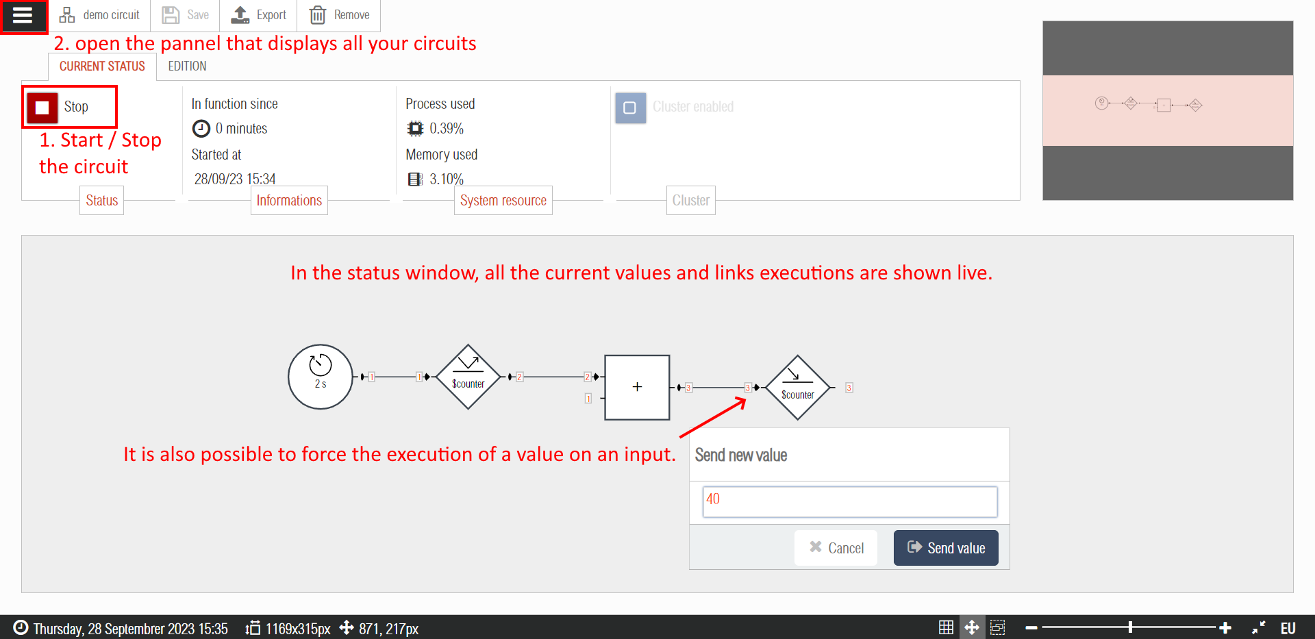
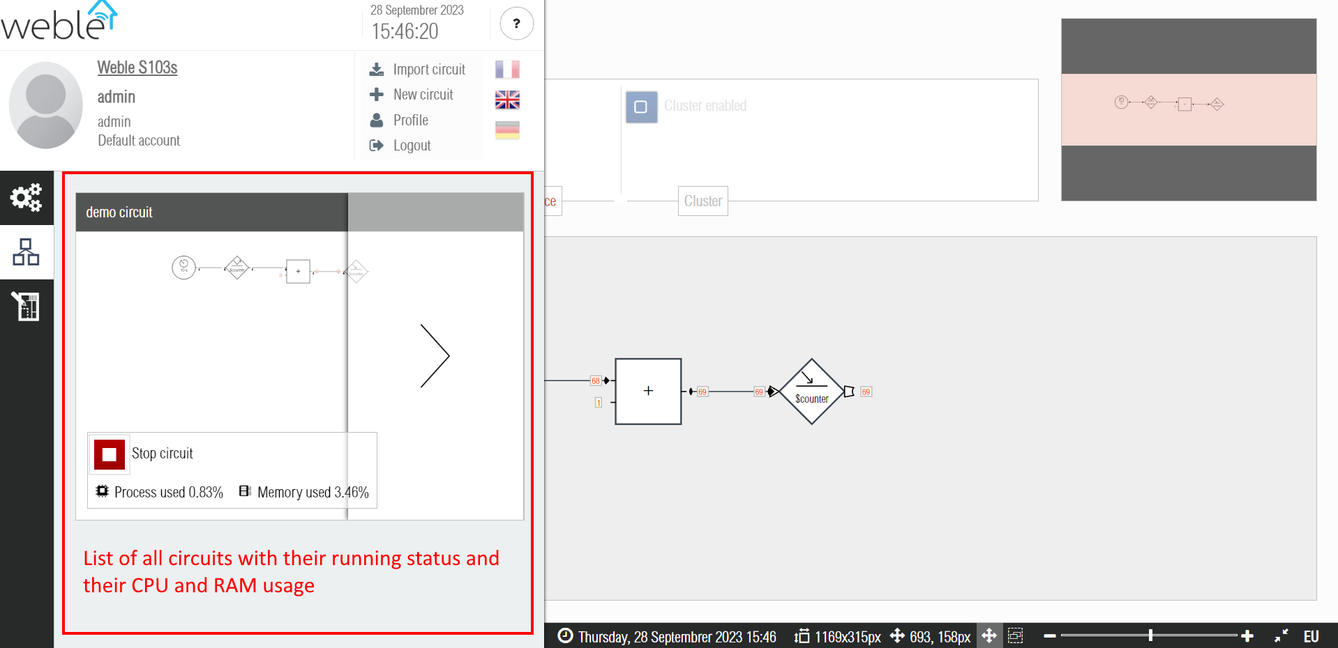
The following serie of screenshots is a quick tutorial that shows in a step by step manner how to use the interface to create a new logic circuit. In this tutorial a counter incrementing its value every 10 seconds is implemented. The counter value is stored in the internal address $counter, so to make the circuit work without errors it is necessary to first insert a gateway of type internal, and then start it (refer to the gateways introduction page for this preliminary step).
¶ 2. Logic circuits
The Weble circuits are an extension of standard logic circuits. They take and extend their functionalities by using simple but effective mechanisms.
The circuits are composed of gates ( Section 2.1 ) connected together by directional links ( Section 2.2 ), carrying values ( Section 2.3 ) and hence triggering the execution.
The interaction with the sensors and the actuators of the KNX bus or the digital inputs /outputs (GPIO) are done through an address system ( Section 2.4 ).
The advanced applications are showed on the last section of this chapter ( Section 2.5 ). Their utilization requires some programmation skills, but allows to solve any use case.
¶ 2.1 Gates
The circuits include around twenty different gates ( Table 1 ), each having several configurable parameters. This flexibility of configuration allows to easily create complex automatisms.
The gates are divided into the following categories :
-
Logic gates :
- Standard logic gates ( Section 2.1.1 ) : basic logic functions as OR/AND.
- Extended logic gates ( Section 2.1.2 ) : logic functions which can handle more than boolean values (1/0) such as numerical values (e.g. 1.234) and text.
-
Triggers ( Section 2.1.3 ) : the triggers wait the realization of an event to start the execution of actions. Moreover, they allow to perform scheduled tasks or to capture telegrams passing on the KNX bus.
-
Actuators ( Section 2.1.4 ): the actuators allow performing concrete actions as writing on the KNX bus and sending SMS and/or emailing alerts.
-
Flow controllers ( Section 2.1.5 ) : the flow controllers act as referrals, helping to control and synchronize the execution flows on the circuit.
-
Other gates ( Section 2.1.6 ) : this last category includes annotations (visual and informative effects) and more advanced gates as the programmable gate ( Section 2.5.4 ).
| Gates by Groups | ||||
|---|---|---|---|---|
| Logic gates |  |
 |
 |
 |
 |
 |
 |
||
| Triggers |  |
 |
 |
|
| Actuators |  |
 |
 |
|
| Flow Controllers |  |
 |
 |
 |
 |
 |
 |
 |
|
| Other Gates |  |
 |
 |
 |
¶ 2.1.1 Standard Logic Gates
The standard logic gates are the graphical representation of basic logic functions. Performing these logic operations, you can check whether some conditions have been filled before initiating an action.
Traditionally, in the Boolean algebra, both input and output data can only have two values : 1/0. Table 2 presents the gates AND, OR, and exclusive OR as well as their truth tables, describing the output value according to the input values.
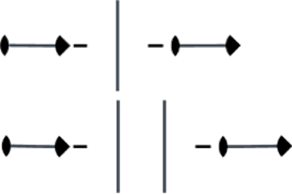
As you can notice on Figure 2, it is possible to reverse the inputs and outputs of these gates as well as include additional inputs.
| Logic Function | European Style | American Style | Truth table | |||||||||||||||
|---|---|---|---|---|---|---|---|---|---|---|---|---|---|---|---|---|---|---|
| AND (n → 1) Outputs 1 only if all inputs equals 1. |
 |
 |
|
|||||||||||||||
| OR (n → 1) Outputs 1 only if at least one of the inputs equals 1. |
 |
 |
|
|||||||||||||||
| XOR (n → 1) Exclusive OR. Outputs 1 if exactly one of the inputs equals 1. |
 |
 |
|

¶ 2.1.2 Extended Logic Gates
The logic circuits not only can treat Boolean values. Also, the links connecting the different gates can carry other kinds of values, such as numbers (integers or rationales) and text strings. The extended logic gates, described in Table 3, offer more flexibility when the standard logic gates cannot fulfil some use case. Figure 3 showcases concactenation of strings for email alerts.
| Description of the logic gate | Graphic |
|---|---|
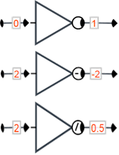
| NOT (1 → 1) The inverter gate allows inverting the value circulating on the link. 3 different kinds of inversion are possible. The binary reverse is 0 if the input is different from 0, and 1 if the input equals 0. The additional inversion is the equivalent of resending on the output –x, where x is the input value. Similarly, the multiplicative inversion equals to resend 1/x. |
 |
| Constant (1 → 1) The constant overwrites the value currently circulating on the link, by setting a constant, default value on the parameters of the gate. Parameters: |
 |
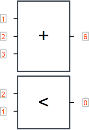
| Calculus (n → 1) The computation gate performs a sum (+), a multiplication (×), an arithmetic mean (μ), or even finds the minimum value (min) or the maximum (max) within the inputs. The comparison operators <, >, ≤, ≥, =, ≠ can also be used. In the case of a comparison, the output provides the result on a binary form : 1 (true) / 0 (false). Note : the sum (+) has a double use as it allows also to concatenate different strings (Exhibit 5). Parameters: |
 |
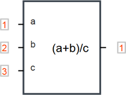
| Expression (n → 1) The expression gate is less constrained than the Calculus gate, and supports the creation of mathematical equations. You can assign to each input an identifier and hence refer to them in the computation. However, the functionality of this gate is not limited just to mathematical formulas, it can perform a variety of other operations (see Section 2.5.2). Parameters: |
 |

¶ 2.1.3 Triggers
Through the use of triggers, you can react to external events (for instance, to telegrams circulating on the KNX module). When the event happens then the output of the trigger is executed. By convention, all triggers are represented as a circle. Table 4 below describes the triggers.
| Description of the Trigger | Graphic |
|---|---|
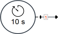
| Timer (0 → 1) The timer starts a new execution sending a span 1 on the link at regular time intervals. It also supports execution at a give date (date format), recurring dates, or other recurring occurences specified using the CRON format. Parameters: |
 |
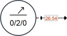
| Address (0 → 1) This gate listens to changes on the configured address (here KNX address 0/2/0). It sends to the output the last value emitted by the communication/bus driver. Parameters: |
 |
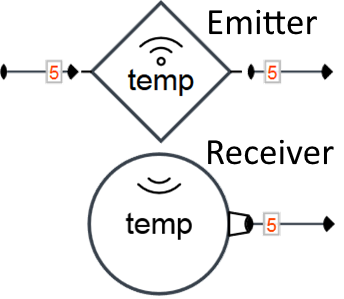
| Receiver (0 → 1) The « Emitter » and « Receiver » gates couple allows the creation of "wireless" links. The Receiver gate captures the values transmitted on the channel given by the configured identifier. As soon as a value is emitted by the Emitter gate on the channel, that value is replicated to the Receiver(s) gate output. Parameters: |
 |
¶ 2.1.4 Actuators
Concretely, the actuators are used to interact (read / write values on addresses) independtly of the protocol / field bus (KNX, Modbus, BACnet, SMTP, ...) such as writing a KNX group address, or sending SMS/email alerts. Actuators have a diamond shape. Table 5 below describes the main actuators.
| Description of the Actuator | Graphic |
|---|---|
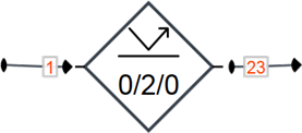
| Read (1 → 1) As soon as the Read gate receives a new input signal, it reads the address (here KNX group address 0/2/0) from the corresponding driver (API call) and sends the respond value to its output. Parameters: |
 |
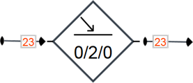
| Write (1 → 1) The Write actuator gate takes as input the value (here 23) to be written on the configured address (here KNX group address 0/2/0). If the telegram has been correctly sent to the bus, the writing value is transcribed on the output. Parameters: |
 |
| Emitter (1 → 1) The « Emitter » and « Receiver » gates couple allows the creation of "wireless" links. The Emitter gate transmits values on the channel given by the configured identifier. As soon as a value is emitted by the Emitter gate on the channel, that value is replicated to the Receiver(s) gate output. Parameters: |
 |
¶ 2.1.5 Flow Controllers
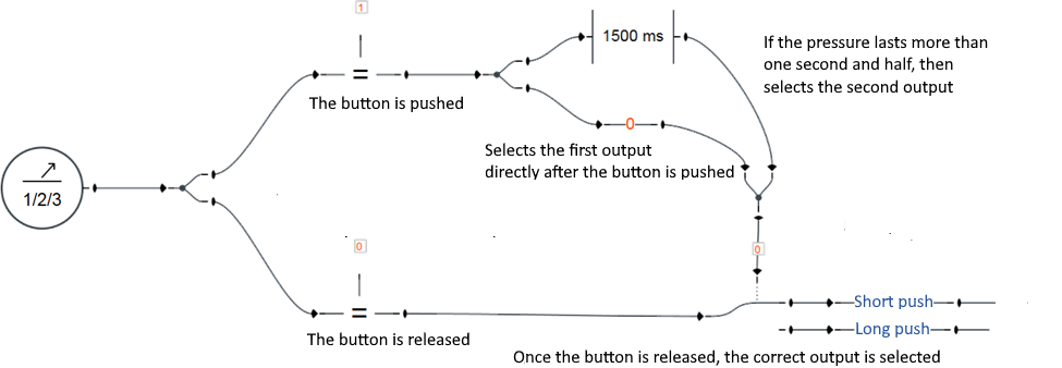
The flow controllers gates permit to connect gates together and to control the execution flow of the circuit. They play a fundamental role by influencing how the values are treated and spread across the circuit. Table 6 describes the flow controllers and the figures below ( Figure 4, Figure 5, Figure 6) provide practical examples.
| Description of the Flow Controllers | Graphic |
|---|---|
| Join (n → 1) The Join gate ties several inputs on the same output. The input values received are directly transmitted to the gate output. |
 |
| Split (1 → n) When an input value is received, it gets replicated and sent simultaneously to all outputs. |
 |
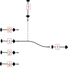
| Input Selection (n → 1) The upper input of the referral allows to select the operating input. The left inputs are indexed starting from 0. For instance, if the referral is configured as 1, then the second input is selected. Parameters: |
 |
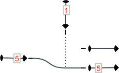
| Output Selection (1 → n) The upper input allows to select the chosen output. For instance, if the referral is set as 1, then the value of the second input (counting from the top towards the bottom, starting from 0) is linked to the output. Parameters: |
 |
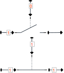
| Switch (1 → 1) If the input of the push button is 1, then the execution of the standard input (on the left) can be transmitted to the output. Instead, if the push button is set as 0, the execution is prevented. Parameters: |
 |
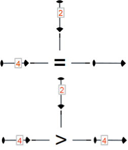
| Filter (1 → 1) The upper input is compared to the standard input (left), and if the filter condition is not verified, then the execution is prevented (filtered out). Parameters: |
 |
| Delay (1 → 1) The delay gate delays the transmission of the execution by a defined timeframe. Different reactions are possible when the gate is reactivated by a new input value before the previous delay has expired. Parameters: |
 |
| Buffer (1 → 1) The buffer gate allows to access to values previously passed through the link. As soon as a new input arrives, the Buffer gate memorizes the new value and sends the previous value to its output, thus introducing a lag effect on the output. Parameters: |
 |


¶ 2.1.6 Other Gates
This category includes some annotation gates (having only a graphical and informative purpose) and more advanced gates such as the programmable gate ( Section 2.5.4 ). Table 7 below describes those gates.
| Description of the Gate (other category) | Graphic |
|---|---|
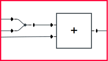
| Group (0 → 0) Can be used to group visually different parts of the logic circuit. This gate is only visual and has no impacts on the circuit function and execution. It has no inputs / outputs. |
 |
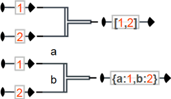
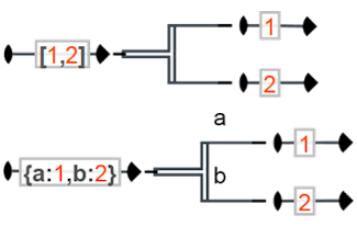
| Fusion (n → 1) Merges together the values received in input on a table (see Section 2.3.3). Parameters: |
 |
| Scission (1 → n) The upper input of the referral allows to select the operating input. The left inputs are indexed starting from 0. For instance, if the referral is configured as 1, then the second input is selected. Parameters: |
 |
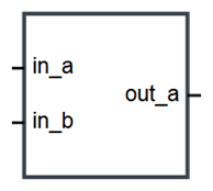
| Programmable (n → m) The programmable gate (Section 2.5.4) is an advanced gate whose logic functionalities can be implemented by using the JavaScript programming language. Its inputs/outputs and its parameters are totally configurable. |
 |
¶ 2.2 Links
The links connect the different ports and transmit the execution through the circuit. There are three kinds of links:
- Memory links ( Section 2.2.1 )
- Passive memory links ( Section 2.2.2 )
- Consumable links ( Section 2.2.3 )
These three link types have different properties that can importantly impact the synchronization of the circuit execution flow ( Section 2.2.4 ).
¶ 2.2.1 Memory Links

The memory link stores always its current value. Once executed, the old value is overwritten by the new one.
¶ 2.2.2 Passive Memory Links

The passive memory link is similar to the normal memory link, but it transmits the execution only if the new value received is different from the old one. For instance, switch of 0 → 1 (incremental flow) or of 1 → 0 (reducing flow) are executed, but repeated executions of the same value such as 1 → 1 are prevented.
¶ 2.2.3 Consumable Links

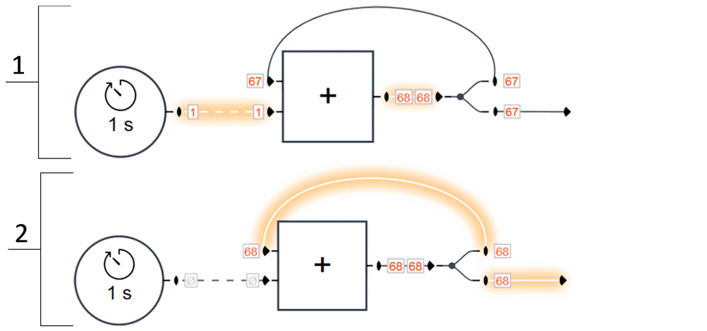
The links connecting the gates can be empty. In this case, the absence of values is marked with the sign ∅. The consumable links, (contrary to the memory links), lose their value (it becomes ∅) when the value is consumed by the targeted gate (i.e. the gate receiving the link end on one of its inputs). A gate normally consumes its inputs when it gets executed and outputs a value, which resets all the consumable links connected to its inputs.
¶ 2.2.4 Synchronization
Before the execution, the gates have to wait for each of their inputs to have a defined value. In other words, if one of the inputs of a given gate is not defined (∅), then its output is not executed (the execution is not propagated to the output link). Figure 7 below shows the use of consumable links to implement a counter.
¶ 2.3 Values
The circuits are not only limited to Boolean values (0, 1). Three main types of values can transit through the links :
-
Numbers : binary (0, 1), integers, or real numbers such as -1.23 ( Section 2.3.1 )
-
Strings : textual values such as "example of string" ( Section 2.3.2 )
-
Arrays : JSON like objects (arrays and associative arrays) such as [0, 1, example of string] ( Section 2.3.3 )
As for the industry traditional logic circuits, these values can be reverted on the inputs and outputs of the ports ( Section 2.3.4 ).
¶ 2.3.1 Numbers
The internal representation of the numbers is always in a double-precision binary floating-point format (64 bits) according to the international standard IEEE 754. In the UI, it is coloured in red.
Regarding the syntax, many different notations are possible :
-
Relative numbers : 0.01, 10.00, -10.505
-
Integers (base 10) : 0, 1, 2, -2, 123456
-
Hexadecimal integers (base 16) : 0xFF ( = 255), 0x12 ( = 18), 0xA ( = 10), -0xA ( = -10)
-
Octodecimal integers (base 8) : 001 ( = 1), 00100 ( = 64), 0077 ( = 63), -0077 ( = -63)
-
Scientific notation : 1e2 ( = 100), -1.2e-2 (= -0.012), 0.0023e+4 (= 23)
-
Special values : PI ( = 3.141…), E ( = 2.718…), ∞, Infinity, NaN (Not a Number)
-
Computational expressions : (sin(PI/4)+0.5)*2 ( = 2.414…), sqrt(5)+log(10) ( = 4.538…). Available functions : https://www.w3schools.com/js/js_math.asp
¶ 2.3.2 Strings
Strings are used to represent textual values. In the UI, it is for most cases strings coloured in blue.
Strings representing system gateway (KNX, modbus, Bacnet, ...) addresses are coloured in green such as the KNX group address 3/2/1 or the modbus register %M1 (see Section Section 2.4 for more information about addresses).
The date format used for the planification of the tasks ( Section 2.5.2 ) is also a string. Those dates are coloured in violet such as 14:00 7.09.2023.
When a string can be mistaken for a number, it is necessary to encompass it between quotation marks (" or ') in order to avoid ambiguities: PI vs "PI", 1.23 vs '1.23', sqrt(5)+log(10) vs 'sqrt(5)+log(10)'.
Strings, using the addition sign (+), can be concatenated to one another, or with numbers, in order to compose new dynamic strings ( Figure 3, Figure 5 ).
¶ 2.3.3 Arrays
Arrays allow to transmit several values through the same link. There is two different kind of arrays :
-
Simple arrays : those are delimited by square brackets [ … ]. The value are separated by commas and each value is referenced according to its position on the table.
Example: [ 1, 2, %M2, [ 3, 4 ] ]. -
Associative arrays : those are delimited by curly brackets { … }. The values are separated by commas and referenced by keys.
Example : { n: 1, m: 2, modbusRegister: %M2, subArray: [ 3, 4 ] }.
¶ 2.3.4 Inversion of the values
By extension of the standard logic circuits, you can revert the values received as inputs of the ports as well as those sent as outputs.
There are three kinds of inversion :
-
Binary inversion : 1 → 0, 0 → 1. By extension a value that is defined and not empty or 0 is transformed to 1, and a value that is not defined or empty or 0 is transformed to 0.
-
Additive inversion : x → -x. Adds the minus sign in front of the number (only works with values of type number).
-
Multiplicative inversion : x → 1/x. Returns 1 divided by the value x (only works with values of type number).
| Value | Binary inversion | Additive inversion | Multiplicative inversion |
|---|---|---|---|
¶ 2.4 Addresses
The « Write » and « Read » actuator gates allow to read and write on the addresses. Using logic module you can treat any address types (refer to the drivers page for the complete list). The following sections shows simple examples using various kind of addresses:
-
KNX addresses (Sections 2.4.1 et 2.4.2) : reads, writes, and captures KNX telegrams on the bus.
-
Modbus addresses ( Section 2.4.3 ) : supports modbus RTU, modbus ASCII, and modbus TCP, and both roles (slave or master).
-
Internal addresses ( Section 2.4.4 ) : permits to store any kind of values internally.
-
Finally the last section ( Section 2.4.5 ) describes how to give an address an alias (alternative name) and discusses the advantages of using aliases in place of raw address names.
¶ 2.4.1 KNX group addresses
KNX, also named Konnex, is a fieldbus and a protocol of automatisms for the building. The KNX protocol is a protocol with a distributed logic. Contrarily to many other automatism protocols, it does not work in a master/slave mode, as each KNX device (sensor or actuator) is mostly independent from the others.
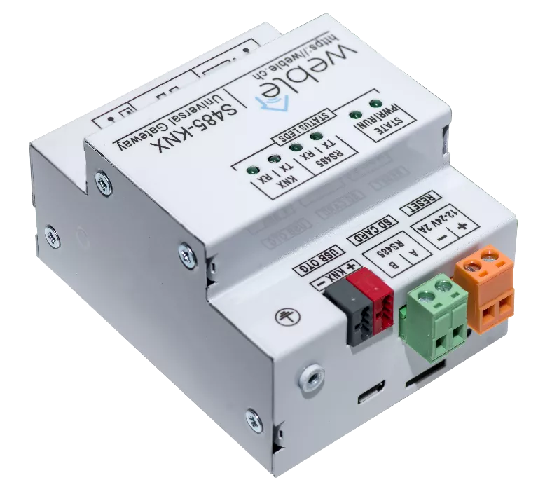
The KNX driver can connect to the KNX bus either through an USB-KNX gateway, a TCP-KNX gateway or directly on the twisted pair (TP) bus if the hardware supports it such as our S485-KNX model ( Figure 8 ).
The communication between KNX devices is assured by telegrams sent on the group addresses. Those ones are used by the sensors and the actuators to transmit data or communicate actions. The group addresses are encoded on 2 bytes. The logic module uses the notation structured into three levels main/middle/sub : 5/3/8 bits respectively ( Figure 9 ).

All communications transmitted on the bus amongst the different participants are captured and sent to the logic module, which then can treat the information and react accordingly by writing on the bus or doing something else. The following actions are supported on the KNX group address.
- Reading of the telegrams flowing through the bus.
- Writing of telegrams on the bus.
- Sending a reading request on the bus and receiving the answer.

¶ 2.4.2 KNX physical addresses
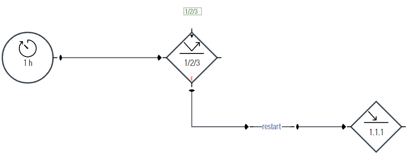
The participants (sensors and actuators) communicating on the KNX bus always have a physical address. A physical address is of the type n.n.n (such as 1.2.3) where the number usually represents a real topology of the building. A physical address is assigned to each device during the configuration / integration phase of the project. Restarting (reboot) a participant can be done from a circuit using its physical address ( Figure 11 ).
¶ 2.4.3 Modbus addresses
Modbus is a serial communication protocol developed by Modicon published by Modicon® in 1979 for use with its programmable logic controllers (PLCs). In simple terms, it is a method used for transmitting information over serial lines between electronic devices. The device requesting the information is called the Modbus Master and the devices supplying information are Modbus Slaves. In a standard Modbus network, there is one Master and up to 247 Slaves, each with a unique Slave Address from 1 to 247. The Master can also write information to the Slaves. Modbus is often used to connect a supervisory computer with a remote terminal unit (RTU) in supervisory control and data acquisition (SCADA) systems. Versions of the Modbus protocol exist for serial lines (Modbus RTU and Modbus ASCII) and for Ethernet (Modbus TCP). For more information, here is a good reference website for Modbus: https://www.simplymodbus.ca
Modbus has 4 types of addresses:
- Holding registers : holding registers are addressed from 0 to 65535, and each holding register contains 16 bits. Each slave has its own holding registers, and those can be read and written from the master (read & write rights). In our addressing scheme, holding registers start with
%Mfollowed by the register number such as%M0,%M1,%M2, ...,%M65535. If we act as the master, the slave number can be specified in the address such as%M1-1is the register 1 of the slave number 1, and%M2-1is the register 1 of the slave number 2. - Input registers : Input registers are similar to holding registers, but the slave input registers cannot be written from the master (read only). In our addressing scheme, input registers start with
%Qfollowed by the register number such as%Q0,%Q1,%Q2, ...,%Q65535. If we act as the master, the slave number can be specified followed by the register number:%Q1-1,%Q2-1, ... - Coils : coils are addressed from 0 to 65535, and each coil contains a single bit. Each slave has its own coils, and those bits can be read and written from the master (read & write rights). In our addressing scheme, coils start with
%MXfollowed by the coil number such as%MX0,%MX1,%MX2, ...,%MX65535. In the same way as for registers, the slave number can be added in the address. - Discrete inputs : Discrete inputs are similar to coils, but the slave discrete inputs cannot be written from the master (read only). In our addressing scheme, coils start with
%QXfollowed by the input number such as%QX0,%QX1,%QX2, ...,%QX65535. In the same way as for registers, the slave number can be added in the address.
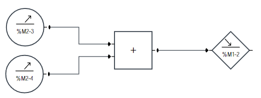
¶ 2.4.4 Internal addresses
Conversely to the other addresses, the virtual addresses are not transmitted on a field bus. These addresses are only for internal uses. They are useful internally to store values, computations, and transmit values between different logic circuits. The internal addresses start with a $ sign, such as $x, $y, or $test123.
¶ 2.4.5 Aliases
No matter the nature of an address (KNX, Modbus, internal, ...), it is possible to define an arbitrary alias (alternative name) for each address. (Note that two or more different addresses can share the same alias for grouped actions.)
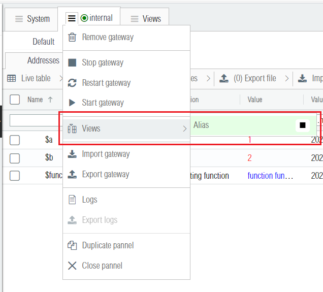
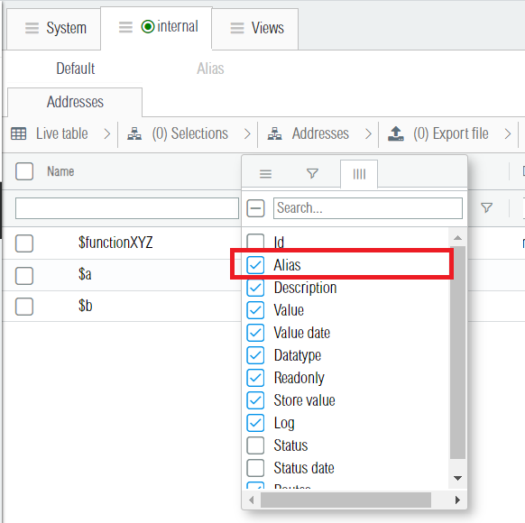
Aliases are running on Views, which is an advanced system that permits to design dynamic alternative address names. Figures 13, 14, and 15 show how to activate and configure the aliases (here the example is on a gateway of type internal, but it could have been of any types (KNX, Modbus, Bacnet, ...).
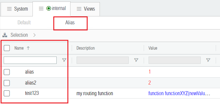
Setting up aliases adds an extra level of indirection/abstraction to the addressing scheme. It presents the following advantages for your logic circuits:
-
Clarity: allows to explicit the meaning of an address on the logic circuit. For instance if the KNX group address
1/1/1is configured to turn on or off the lights of a room, for readability it is clearer to refer to it by using an aliaslight_room_1which conveys more information to the user / technician. -
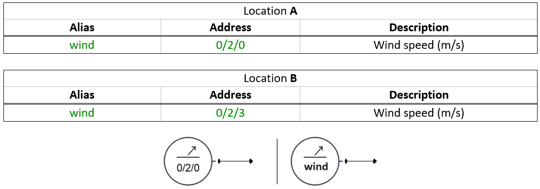
Portability: allows to transfer the logic circuits from one location to another, even if the KNX addresses used are different. For instance, if the wind speed measured by an anemometer is transmitted on
0/2/0to the locationAand on0/2/3to the locationB, then for portability reasons it is more practical, on the two cases, to access to it by using the common alias wind (see Figure 16 below).
- Solves address name conflicts : when several gateways have addresses with same names, it becomes necessary to differentiate those. For instance if there is 2 KNX gateways (gateway
A, and gatewayB), and in each of the two buses the wind speed is measured and communicated on the group address0/2/0, then it is possible to distinguish the addresses by assigning to each a different alias, as shown in Figure 17. (Note that it is also possible to solve a name conflict without aliases. With the special character¬it is possible to define the gateway name in the address name, such asA¬0/2/0is the knx group address0/2/0of the gateway namedA, andB¬0/2/0is the same address, but the one used on the KNX lineB).

- Grouped actions : it is possible to assign the same alias to different addresses, and then use that single alias in the logic circuit to perform group actions on all the addresses having that common alias. Note that a single address can have multiple aliases by using the separator character
¬between each alias when editing the alias column (i.e. if an address has the aliasX¬Y¬Z, it has in fact 3 different aliases:X,Y,andZ).
¶ 2.5 Advanced Functionalities
The command of the advanced features requires more skills but allows to operate in all kinds of situations. The following topics will be covered :
-
The advanced mode ( Section 2.5.1 ), which is present on some of the gates, displays previously hidden advanced inputs/outputs. The advanced mode enables more features and dynamic control of some gate parameters.
-
The tasks scheduling ( Section 2.5.2 ), which explains how to schedule unique or periodic tasks.
-
The advanced expressions ( Section 2.5.3 ). This section shows more powerful ways of using the « Expression » gate.
-
The programmable gate ( Section 2.5.4 ), with which you can create your own custom gates in JavaScript.
¶ 2.5.1 Advanced Mode
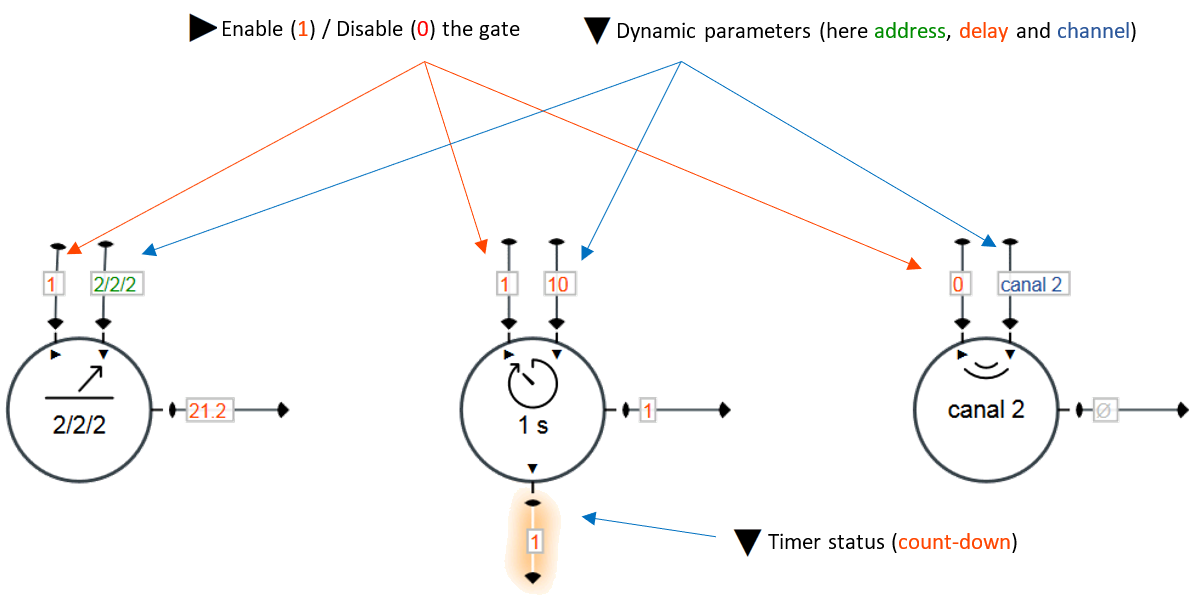
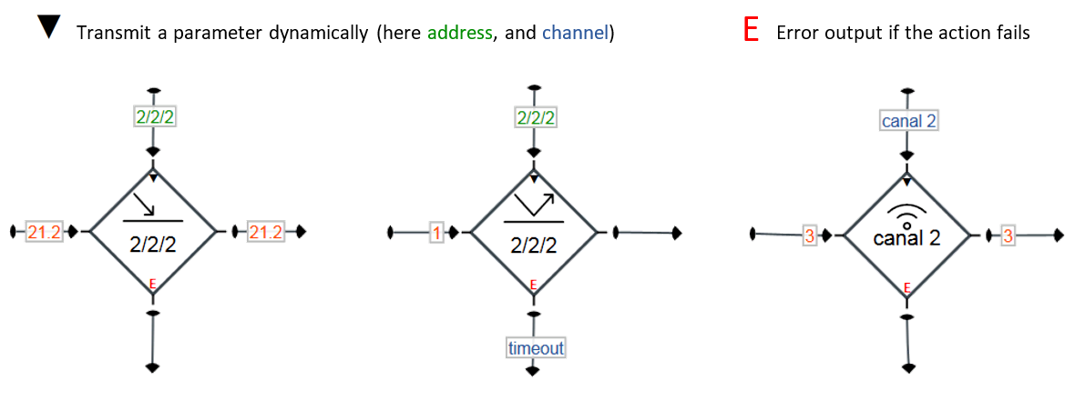
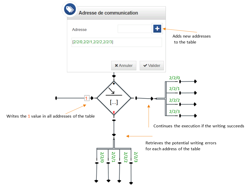
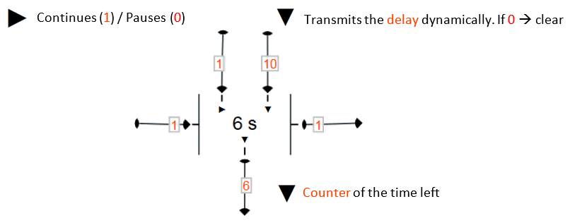
The advanced mode, when it is activated on a gate, adds inputs/output to the gate. It lets you dynamically control the gate during the circuit execution : enable it, disable it, pause it, or change its parameters. The following gates support the advanced mode :
¶ 2.5.2 Task Scheduling
The task scheduling can be done by using the « timer » gate. The timer gate includes different kinds of values ( Figure 22 ) :
-
The number (positive integers), allows to repeat an action each x milliseconds/seconds/minutes/hours/days.
-
The dates ( Table 10 ), allowing the scheduling of a task at a defined date.
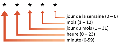
-
The cron format ( Figure 23, Table 11 ), which is the format used by UNIX OS for scheduling recurring tasks.



¶ 2.5.3 Advanced Expressions
The expression gate is not limited only to simple formulas as (a+b)/2. Instead, an expression actually is a line of code interpreted by the JavaScript engine. This gate makes possible a number of operations on the values :
-
Logic operations and comparisons. For instance :
(a > b && a > c) || a == 0returns1if a is bigger thanbandc, or ifaequals0. Otherwise it returns0. -
Ternary operator:
a == b ? 10 : -10returns10ifaequalsb, and otherwise0 -
Call native JavaScript mathematical functions such as :
acos(x) asin(x) atan(x) atan2(y,x) ceil(x) cos(x) exp(x) floor(x) log(x) max(x,y,z,...,n) min(x,y,z,...,n) pow(x,y) random() round(x) sin(x) sqrt(x) tan(x) -
Call string functions such as :
charAt() concat() indexOf() lastIndexOf() match() replace() search() slice() split() substr() substring() toLowerCase() toUpperCase() trim() -
Use regular expressions :
/eat.*cheese/.test("I eat swiss cheese")returns 1. -
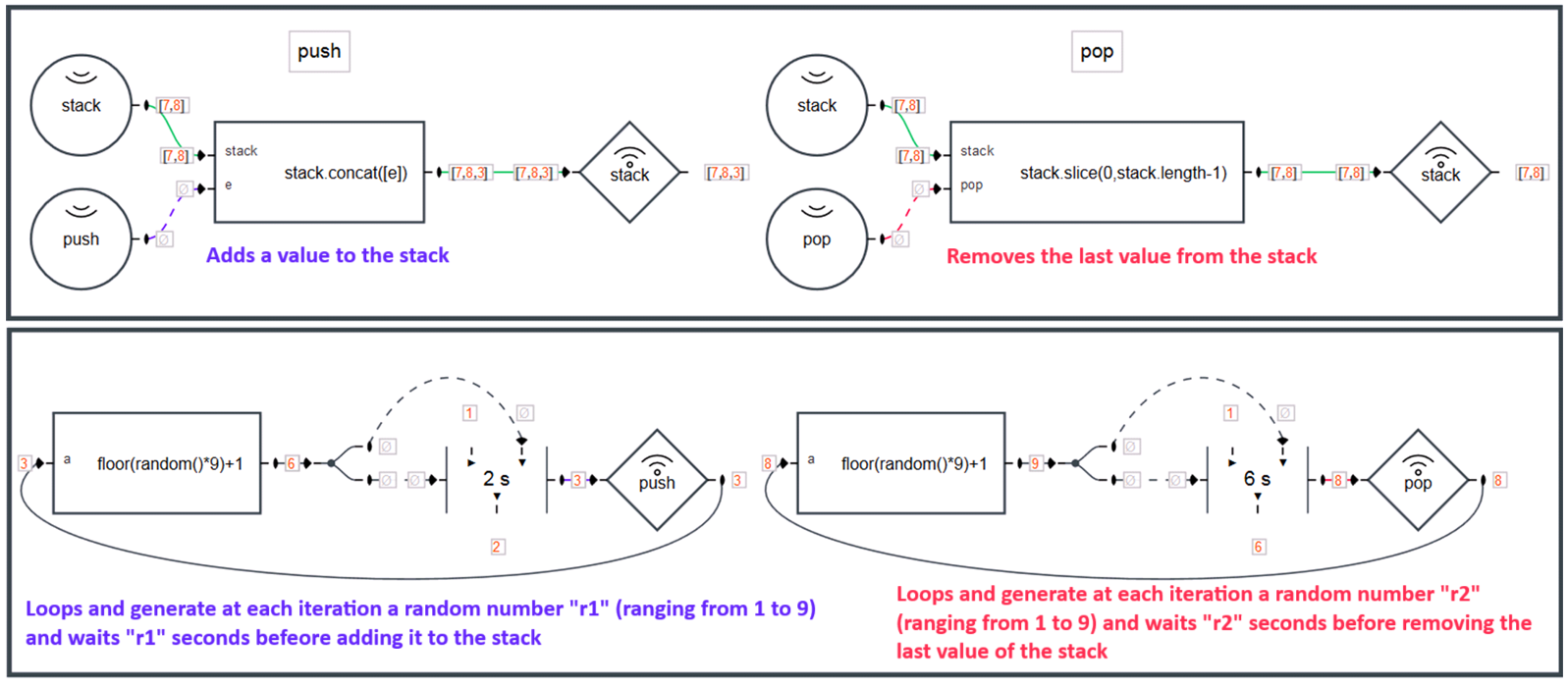
Call functions to work on arrays :
concat() every() filter() join() map() reduce() reduceRight() reverse() slice() some() sort() …
Figure 24 shows how to work on an array of values using expressions. -
And many other applications...
¶ 2.5.4 Programmable Gate
The programmable gate permits to create custom made gates using the JavaScript programming language. This powerful programming tool can be used to fullfill virtualy any tasks / use cases.
The list below goes through some key features offered by the programmable gates :
-
Export & Import capabilities let you re-use implemented gates across different projects.
-
Unlimited number of custom inputs and outputs.
-
Unlimited number of custom configurable parameters.
-
Access to JavaScript native objects (
Object,Array,Buffer,Math,String,Date, …). -
Access to useful node.js modules such as:
assert,buffer,crypto,dgram,dns,domain,events,http,https,later,net,os,path,stream,string_decoder,suncalc,tty,url,util,zliband more. -
Ace code editor (a web-based JavaScript code editor) integrated with the automatic detection of errors and auto-completion.
-
A console showing information useful for the debugging.
The following figures demonstrate multiples use-cases:
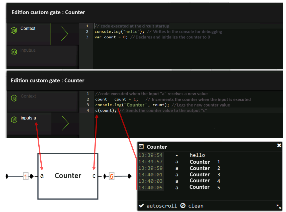
- Figure 25 shows the basic implementation of a counter, and Table 12 explains how to access the value of an input and execute an output from the programmable gate code.
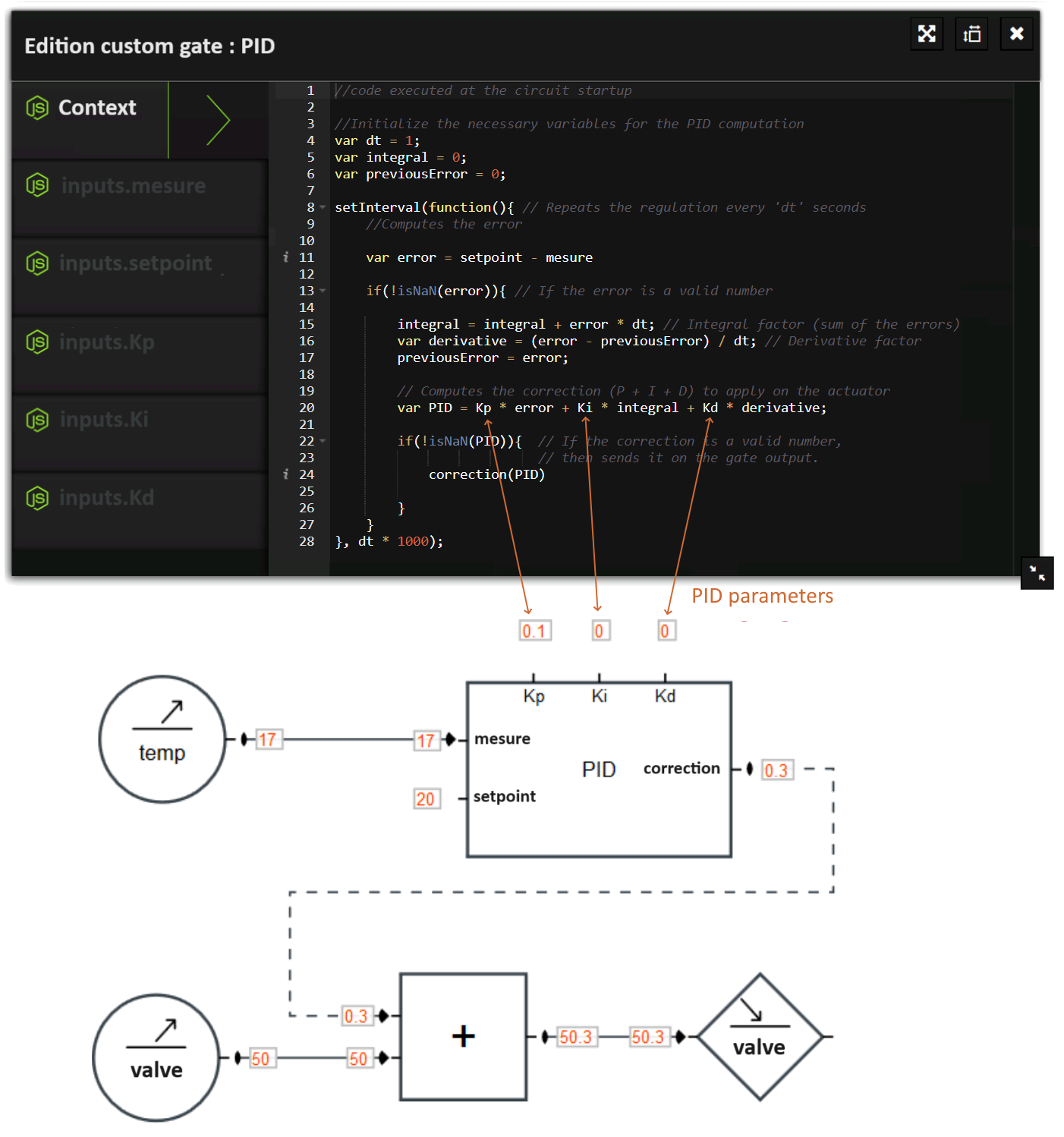
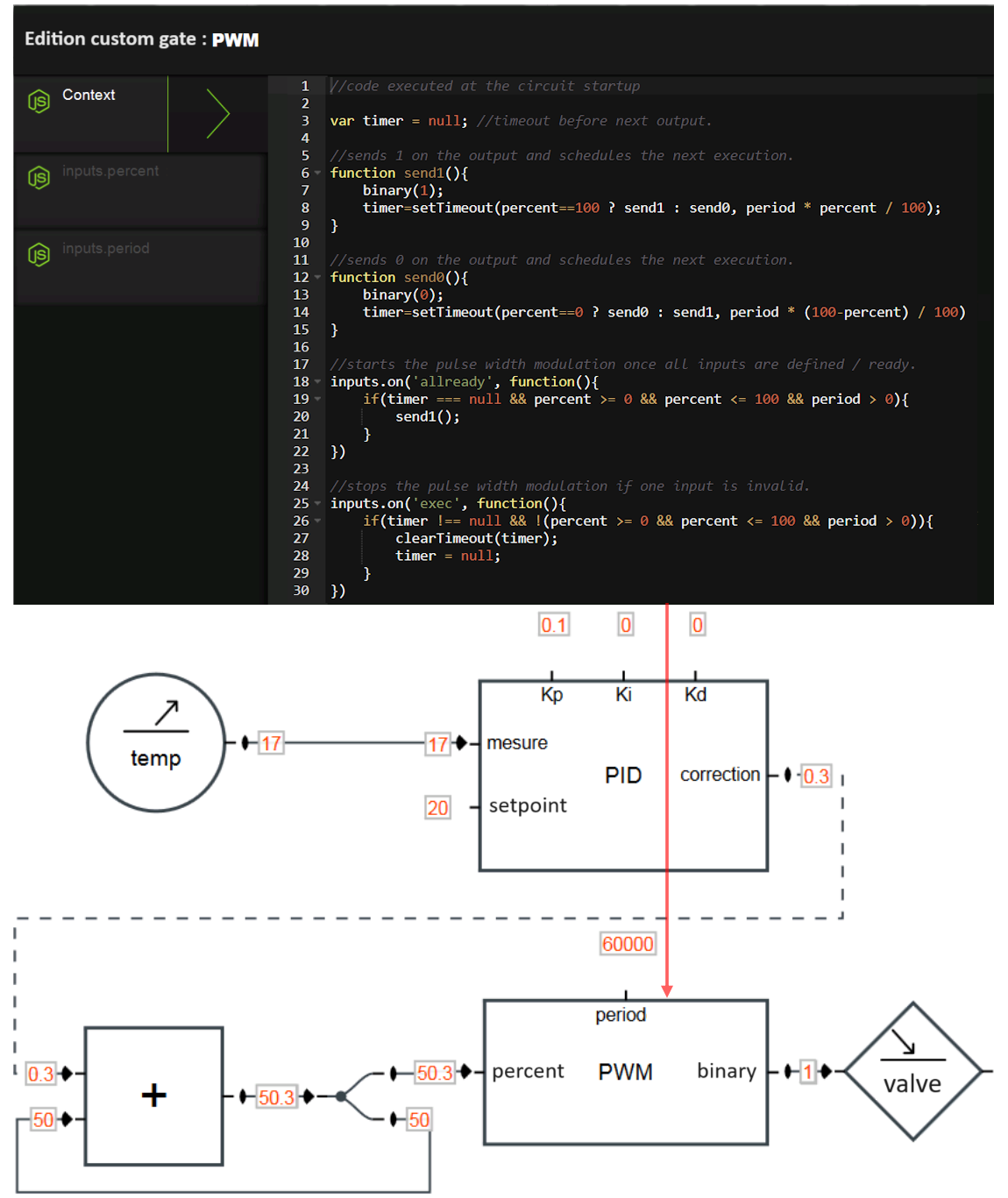
- Figure 26 (PID controller) and Figure 27 (Pulse Width Modulation) show two examples of the use of programmable gates for room temperature regulation.
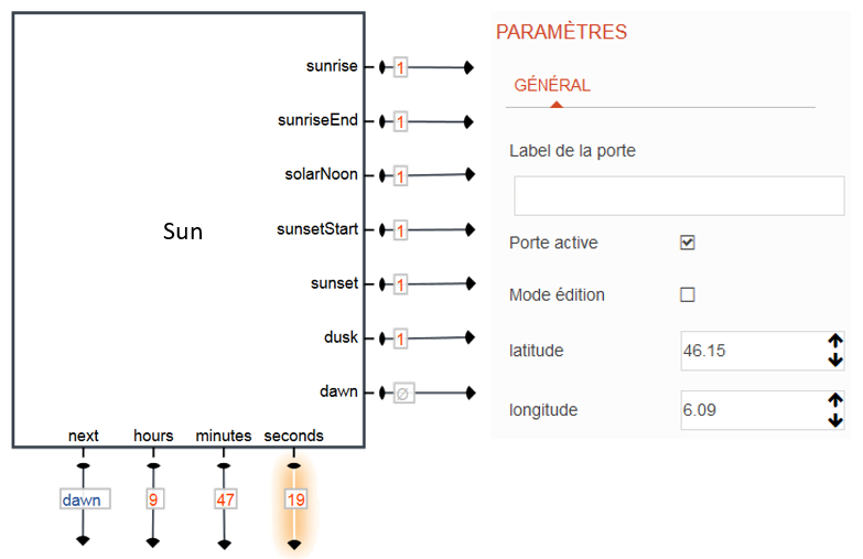
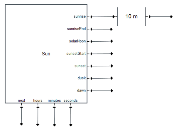
- Figure 28 illustrates a gate useful in home automation which calculates the time of sunrise and sunset from the latitude and longitude. This gate is practical for carrying out actions at particular times of the day (raising blinds in the morning, lowering the blinds in the evening, turning on lights, closing a door, etc.). The implementation ( Table 13 ) uses the
suncalcmodule to perform solar calculations. Note: the calculations do not take into account the relief which could, for example, delay sunrise by a few minutes. If this is the case, a delay can be added using adelaygate ( Figure 29 ) or directly in the code.
Access to the input a value |
Executes 1 on the output c |
|---|---|
Gate.inputs.a.value |
Gate.outputs.c.exec(1) |
inputs.a.value |
outputs.c.exec(1) |
a |
c(1) |
var suncalc = require('suncalc'); //https://github.com/mourner/suncalc
var nextTimer = null;
//schedules execution of next event (sunrise/sunset/...)
function scheduleNextEvent(startTs){
    var now = Date.now();
    //compute events timestamps based on latitude and longitude parameters
    var res = suncalc.getTimes(startTs ? startTs : now,latitude,longitude);
    var keys = outputs.filter(function(o){return o.position == 'right'}).
                                map(function(o){return o.name});
    var tss = keys.map(function(k){return res[k].getTime()});
    var tsMin = tss.map(function(ts){return ts < now ? Number.MAX_VALUE :ts}).
                                reduce(function(a,b){return Math.min(a,b)});

    if(tsMin !== Number.MAX_VALUE){ //timestamp of the next event found
        var indexMin = tss.indexOf(tsMin);
        var output = outputs[keys[indexMin]];

        nextTimer = setTimeout(function(){ //executed when the event happens
            output.exec(1); //send an impulsion to the correct output.
            scheduleNextEvent();
        },tsMin-now);

        next(keys[indexMin]); //indicates the next event(sunrise/sunset/...)
    }
    else{ //all the events (sunrise/sunset/..) are past for today
        scheduleNextEvent(now+1000*60*60*24); //find tomorrow next event
    }
}
//countdown until next event (sunrise/sunset/...)
function countdown(){
    var tsl = Math.round(nextTimer.next()/1000); // total seconds left
    var s = tsl % 60; // seconds left
    var m = Math.floor(tsl/60) % 60; //minutes left
    var h = Math.floor(tsl/3600); // hours left
    seconds(s); //outputs the seconds left
    if(this.m != m){ //outputs the minutes left (when it changes)
        this.m = m;
        minutes(m);
    }
    if(this.h != h){ //outputs the hours left (when it changes)
        this.h = h;
        hours(h);
    }
}
scheduleNextEvent(); //start at initialization
countdown(); //update coutdown at initialization
setInterval(countdown,1000); // update countdown every seconds